Enhancing Situational Awareness with Remote Sensing: Using Synthetic Aperture Radar (SAR) Images for Defence & Intelligence (D&I) Applications
Dr. Dipak Paudyal
The proliferation in the availability of remotely sensed (RS) data creates challenges and opportunities for defence and intelligence (D&I) organisations worldwide. This deluge of big data includes high-volume and high-resolution video, satellite, and aerial imagery, non-optical data such as LiDAR and SAR, and unstructured data such as social media feeds and document archives. Advanced technologies that can manage, discover, fuse, analyse, and transform this data into actionable intelligence and quickly disseminate it hold the promise of tactical and strategic advantage.
The focus of this white paper is on the GEOINT applications of one such data type namely Satellite-based Synthetic Aperture Radar (SAR) data. GEOINT application of SAR is not new, it has been around for years. There have been several commercial SAR systems operated by organisations such as Airbus, MDA, E-GEOS, ESA and JAXA. While there are also national satellite launches for defence and security that are not available for public use, this whitepaper will limit its discussion on use of SAR data acquired by commercial sensors and their capabilities. In principle, the application areas are very similar.
We have seen that many commercial satellite vendors and government organizations have launched or are planning to launch SAR systems that can be used by the D&I community. Figure 1 below, while not exhaustive, provides a list and timelines of proposed SAR satellites that have been launched or will be in the very near future.
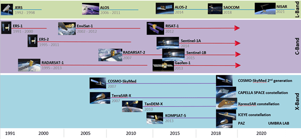
Figure 1: SAR Satellite Missions Past and Future (Source: L3Harris Geospatial)
The increase in launches of SmallSat’s or MicroSat’s with SAR sensors mimics that of optical satellites (e. g. Planet). These lightweight commercial SAR sensors has created significant opportunities for the D&I community. The opportunity arises because the radar satellites can now frequent an area with a very high revisit rate. More importantly, these sensors would allow for guaranteed acquisition of data, since SAR is an active system, it can operate day/night on a 24/7 basis and can acquire images relatively unhindered by rain, cloud, and other local adverse weather conditions.
It means that monitoring an area, activity, event, or a phenomenon does not need to wait for more than 24 hours in most instances. There could not be a better time to utilise SAR data for situational awareness. When the near real-time information obtained by these SAR systems is combined with available electro-optical and other ancillary GIS and human intelligence data, it can be a wealth of information for the D&I community.
The opportunity provided however does not come without challenges. While satellite-based SAR technology is a great asset for GEOINT applications, the need to process, store, manage and analyse the data are significant, and markedly different to how optical data can be utilised for similar tasks.
The foremost challenge is to manage the volume of the data. For GEOINT communities that are familiar with handling SAR images – the very fact that there are many satellites that can offer higher frequency of revisit and wider coverage means the enormous amount of data generated is a challenge. Then there is a need to store or archive the data and discover it on demand. This makes managing this huge volume of data challenging.
A unique feature of SAR is that every “band†of the data potentially comes in two separate layers, which are – intensity and phase. These are often complex data types and require pre-processing to get into formats that are friendly to end users. More important, many D&I GEOINT applications require exploiting phase information and many applications require a multitemporal monitoring over an area to arrive at actionable information. This only increases the volume of the data for storage, management, and analysis of the data.
In summary, even organisations with fully operational image processing and analysis capability that are used to exploiting optical imagery may not be fully prepared for the incoming avalanche of SAR data. This whitepaper looks at the GEOINT applications that can make use of SAR and empower the D&I community to achieve enhanced situational awareness – both in the short, medium and the longer-term horizon.
Let us first recap on electro-optical RS technology which is already used extensively in a wide variety of military and intelligence applications. Typical military and intelligence applications using Optical RS include:
- Locate specific targets: By shape (e. g. object-based classification or Deep Learning) or spectral properties (spectral classification), e. g. identify roads and vehicles, or locate specific materials of interest
- Detect partially hidden targets: Camouflaged objects, tanks hidden under tree canopies, etc.
- Analyze terrain –
- Elevation images can be used to find steep areas, passes, etc.
- Line-of-sight analysis can determine which areas can see and be seen by field personnel at known locations.
In addition, techniques for optical RS allow D&I personnel to extract key features of interest that may be required for an operation, categorise terrain, and automatically create map products often from advanced sensors to complement existing commercial satellite imagery.
Defence personnel are often mobilised by respective governments to support the civilian effort during times of natural and human-generated disasters. It is in this context, GEOINT applications that are often relevant to assist natural and human-generated disasters such as:
- Detect damage after disasters: Oil spills, forest fires, landslides, hurricanes, floods, tsunamis, volcanoes also come into play.
- Monitor hazards, predict, and plan for disasters.
The D&I community can greatly benefit by using SAR data to compliment the optical RS capabilities for the tasks that are listed above. Given the day night imaging capability of SAR sensors, SAR may be the only option available for some of these applications!
In addition, cloudy skies, smoke, dust, and other vision obscuring conditions often limit the support capabilities from overhead aircraft and satellite based optical sensors. Airborne weapon systems that use electro-optic and infrared (EO/IR) sensors during support missions/disaster recovery cannot ‘see’ through clouds. SAR can again come to rescue and help overcome those limitations. The graphics in Figure 2 presents some of the capabilities SAR systems provide (of course the list is not exhaustive)! These are discussed in more details in the section following:
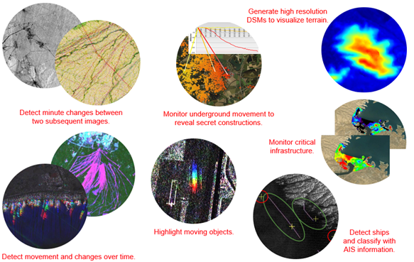
Figure 2: Typical D&I Applications of Synthetic Aperture Radar (SAR)
Detecting Changes
Detecting changes between two or more dates is the crux of many GEOINT applications. It is really the holy-grail – what we can detect, when we can detect, and how accurate we are in this detection involves a combination of data, analytical and processing skills, and any additional intelligence to complement the observed phenomenon that we can pour into the system. Another important aspect of the change detection paradigm is how automated is the process and if the changes can measure and provide us with both qualitative and quantitative reports.
Qualitative reports can be used by senior commanders and policy makers and quantitative reports are required by boots on the ground or those who would like to glean fine details. When it comes to detecting changes, no other sensor can beat SAR simply because its ability to see at night and through cloudy skies, smoke, dust, and other vision obscuring conditions. And, the ability of SAR sensors to gather data from an altitude of 500 Km+ provides a massive advantage to anyone who understands and can use this technology to detect changes.
As we know SAR can capture two types of information – amplitude (or scene intensity) and the phase (of the SAR signals sent and received). Let us first look at simpler cases of amplitude-based change detection.
Change Detection – Ship Movement
SAR data can be used to detect ships because of differences in how the radar signal is returned to the sensor. The radar signal can experience diffuse, specular, or double bounce backscatter, depending on the type of surface it interacts with. Smooth water bodies, such as the ocean produce specular reflections, where most of the radar signal is reflected away from the satellite. This creates dark pixels in a SAR scene. Ships in water produce a double bounce, which returns most of the radar signal to the satellite, and results in bright pixels in a SAR scene. A study (Figure 3) was conducted by sarmap SA (developers of SARscape software) using three Cosmo-Skymed scenes and ENVI® SARscape®. The data was acquired on (a) May10 (R), (b) May 26(G) and (c) June 03 (B) in 2009. The third scene (June 3) had a low tide during the date of capture.
When the 3-scenes are displayed in R, G, B as colour composites, we can make very interesting observations as follows:
Ships seen in Yellow (R+G) were present at the port on 10 and 26 May 2009.
Ships seen in Cyan (G+B) were present at the port on 26 May 2009 and 03 June 2009
Ships seen in White (R+G+B) were stable all over the period of analysis.
While this is a more simplistic analysis, the result and interpretation can be made on various other combinations of events. In this instance (Figure 3d), there are only three observations, so we can easily interpret the meaning of colours and what these could mean, but we could also automate the entire activity monitoring process using artificial intelligence (AI) and image processing tools! This would provide the D&I community with a valuable set of information that can be gathered routinely over an area of interest. The same technique can be used for activity monitoring on any part of the world on any ocean/sea as part of a more ocean comprehensive surveillance system.
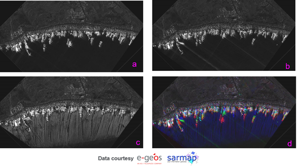
Figure 3: Change detection using SAR amplitude.
Coherence Change Detection
We have come across this situation many times; when we need to look at a particular area of interest, we find that there is absolutely no cloud free image over that area or the information we would like to get cannot be clearly seen in this imagery. Here is one such situation.
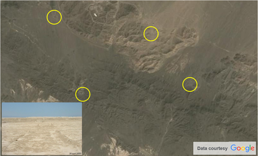
Figure 4: Uranium enrichment facility in Iran
Figure 4 shows four known locations of uranium enrichment facilities in Iran. Looking at the optical imagery it is almost impossible to say if there are active transportation networks between these enrichment facilities. The inset figure(5e) shows the nature of the road track in the terrain that literally merges with the desert surroundings. It would be almost impossible to find clearly defined vehicle tracks that provide enough contrast to the surrounding environment so these can be detected (either visually or automatically using techniques of image analysis or AI) from the optical image alone.
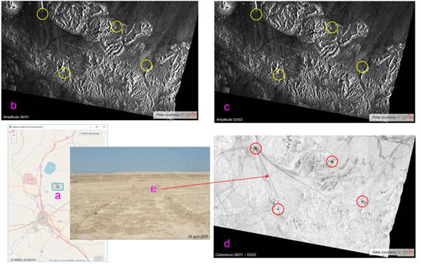
Figure 5: Identifying transport networks using SAR coherence change detection (uranium enrichment facility, Iran). Data courtesy of e-geos.
SAR comes to the rescue one more time. This time we are not interested in the amplitude (or intensity) of SAR image as those images would not be useful and would be like a panchromatic image at best. However, the phase image acquired by SAR will enable us to map the vehicle tracks precisely, because now we are not relying on the brightness of the pixel but relying on the tiny movement of the soil surface caused by vehicles. This example highlights how SAR can overcome the challenge of performing change detection in areas where optical data alone is insufficient.
When an area on the ground appears to have the same surface characterisation in all multi-date images under analysis, the images are said to be coherence. The coherence is a measure of the change (decorrelation) between two or more SAR acquisitions and calculations use the phase information to detect changes. The estimated coherence – which is dimensionless and ranges between 0 (black = complete decorrelation) and 1 (white) – is a function of systemic spatial de-correlation (i.e. the additive noise) and temporal de-correlation between two or more acquisitions.
Figure 5 shows the general location of the area in a study conducted by sarmap using ENVI SARscape (b) and (c) SAR imagery captured at two different dates, 26 January and 3rd February. (d) is the map that shows the result of coherence change detection that clearly depicts linear features showing vehicle movement between the centers. In this scenario, we suspect activity is taking place, however, our optical analysis is inconclusive and SAR data has allowed us to arrive at a conclusive result.
A little closer look at the coherence map shows the use of dirt roads, and points of connections active between these dates. Here the coherence shift detected is caused by the textural change from vehicle tracks in the sand which are not spectrally distinct! So, SAR coherence change detection can be used to detect activity which may have insufficient spectral variance for optical detection. In addition, this example exemplifies detection of features due to changes in the surface condition (e.g. change in soil/dirt condition) that has many other applications.
SAR Oil Spills Detection
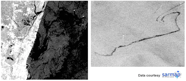
Figure 6: Oil spill detection using SAR (a) India (b) Sweden
We often hear about oil spills in our waters, mostly in routes navigated by ship tankers carrying oil. Oil spills can also happen in and around offshore drilling rigs. Oils spills are clearly environmental disasters when they happen as it can cause massive damage in the form of polluting the water and killing of wildlife and ocean dwelling flora and fauna. From a national security point of view, oil spills can also be indicative of some political/military event and can manifest itself in the form of oil smuggling operations, collision of two or more tankers or ships, or some other clandestine maritime activity that could happen day or night.
Oil creates a heavy sheen on the water surface, which differentiates it from surrounding water. In SAR data such as Sentinel-1, oil spills have a very different surface tension than water, making them stand out against background water response. Polarisation is important, and the VV (Vertical send and Vertical receive Radar signals) polarisation is a good choice for viewing surface changes on water, if there was an option of polarised SAR data.
Let us illustrate this with a study conducted by our partner sarmap using two examples (Figure 6); the first is the Ennore Oil spill shown on the left image. This oil spill happened in early 2017 and occurred from the collision of two oil tankers outside of Kamarajar Port near Chennai, India. An oil slick was seen surrounding two vessels, and the shore was later confirmed to have tar balls and oil residue that affected the local wildlife. Sentinel-1 scenes are shown.
The second example in Figure 6 is an oil slick outside Gotland Island, Sweden. The cause of this oil spill is unknown but is readily apparent in the patterns that are seen. ENVISAT is used for this data set and illustrates the power of SAR for measuring foreign substances in the ocean. Interestingly if we also knew approximate thickness of the oil layer, it is a straightforward task to measure the total quantity (volume of oil) spilled in the ocean.
In addition to oil spill detection, there are many other things that can be done with SAR in the ocean such as identify waves, shallow bathymetry, wind effects on the surface of water, and identifying other surface coverings, such as plant matter.
SAR Ship Detection (Feature Extraction)
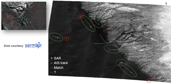
Fig 7: AIS marine traffic information and SAR ship detection
In addition to using SAR to detect ships, AIS (Automatic Identification Systems) can be used to compare results. Since 2003, regulations dictate that all vessels over 20m / over 300 Gigatons must be equipped with an AIS transponder. While AIS beacons are required to be always transmitting on large ships, sometimes ships turn these signals off, or alter them to report a different location. The combination of SAR ship detection and AIS tracking can identify ships that were detected in the SAR scene, but not the AIS data – indicating potentially unsavory activities.
Figure 7 shows one of the studies done by Sarmap depicting a SAR AIS classification on a RADARSAT-2 scene over Nuuk, Greenland. Yellow crosses mark ships that were detected in the SAR data, while purple lines show the AIS data of ship tracks. Green circles show ships that match in the SAR and AIS, while red circles indicate ships that were identified in the SAR data, but do not match up with any AIS tracks.
- AIS is spoofed or disabled for reasons such as:
- IUU fishing (Illegal unreported and unregulated fishing)
- Sanction violation: AIS is particularly often turned off close to sanctioned countries.
- Illegal oil spilling (oil spills can be also well detected from SAR)
From a GEOINT point of view, the main motivation is maritime domain awareness and border and asset monitoring for dark vessel detection or detection of anomalous vessel behavior. Fusing SAR and AIS data enables detection and correlation, and then followed by optical/SAR high resolution images allow us to identify /classify suspicious vessels (e. g. Deep Learning).
One note of caution, AIS often does not work well in heavy trafficked area, and as a result, terrestrial AIS (instead of satellite based AIS) is used in such areas to detect ships.
Monitoring of Land Displacement Activity
A unique capability of SAR processing software, such as ENVI SARscape, is the generation of Digital Elevation Models (DEMs) using techniques of InSAR ( or StereoSAR) and creation of surface deformation maps using techniques of DInSAR. Such state-of-the-art methodology generates accurate and detailed surface and terrain height products. I once had a person call me and tell me they needed to urgently create a DEM over an entire country because a good quality DEM was not available, and they needed it to visualise the terrain and carry out some 3D simulations. I was asked what the easiest option was to build something quickly. I was quick to suggest generating a DEM using tandem ERS-1 InSAR at that time. Figure 8 shows how such a DEM would have been possible to create, using an example of results conducted by our technology partner Sarmap using ENVI SARscape.
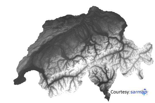
Figure 8: DEM of Switzerland based on ERS-1 Tandem data. Vertical resolutions vary based on topography. 95% DEM derived using SAR data. © ERS data, ESA
In some instances, GEOINT applications can make use of DInSAR techniques that can detect centimetre-scale displacements over time spans of days to years. The DInSAR method of interferometry is applicable in geophysical monitoring of natural hazards like earthquakes, volcanoes, and landslides. It is also useful in structural engineering, particularly for the monitoring of subsidence and structural stability.
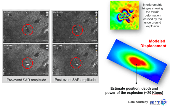
Figure 9: Monitoring activities at the U.S. Nevada Nuclear Experiment Test Site using SAR interferometry.
Figure 9 shows SAR based displacement analysis of final nuclear test detonation at the Nevada Test Site was Operation Julin’s “Divider” on September 23, 1992, just prior to the moratorium temporarily ending all nuclear testing. “Divider†was a safety experiment that was detonated at the bottom of a shaft sunk into Area 3.
The interferometric processing allows us to quantify the terrain displacement. These are all ERS-1 images, and the pair across the event 11/09/1992 – 25/12/1992 has been processed with the DInSAR technique by sarmap using ENVI SARscape. The Non-linear inversion model has then been used on the generated displacement map to identify the parameters of a Mogi (point pressure), namely location (Lat-Lon), height (depth) and amount of volume change, that then be converted into equivalent kilotons.
The top right image shows Interferometric fringes derived from DInSAR and shows the terrain deformation caused by the underground explosion. The bottom right figure shows the inversion of geophysical models and allows us to estimate the position, depth, and power in Kilotons of the explosion. For operation Julin’s “Divider” detonation the estimated power was some 20 Ktons.
While the usefulness of what is often referred to as n-Pass Interferometry utilizing few scenes is useful for detecting displacement due to events such as nuclear detonation or earthquakes, there are times where the deformation of land surfaces can be subtle and need monitoring over a longer period. Such displacement may be the result of underground activities, such as tunneling.
In some instances, there may be a need to monitor critical infrastructure to see if it is stable or if there are any security risks. The monitoring of tailing dams in mining areas is a good example of such monitoring that requires a very large number of SAR scenes acquired over a longer time frame. This technique of utilizing multitemporal SAR images is often called Interferometric Stacking technique and can model and detect movement of the ground surface (subsidence or uplift), as small as a few centimeters. Such movements are often described in units of movement over time (or the velocity of movement) to signify changes over a certain time period.
ENVI SARscape uses point-based (PS-like) and area-based (SBAS-like) techniques for the processing of interferometric stacks. This combined approach enables users to obtain accurate results on both point and distributed targets.
Persistent scattering techniques of Interferometric stacking enables users to detect very small displacements (mm scale) and to infer the deformation velocity – and its variation over the time – for very stable (man-made) reflectors that might have independent displacements in respect to the surrounding areas.
On the other hand, a complementary method that exploits Differential Synthetic Aperture Radar interferometry (DIfSAR) techniques to analyse stacks of SAR acquisitions to extract small deformations over large areas, when no point targets are identified but large, correlated displacements occur over natural targets is implemented as SBAS (small baseline subset) technique. By combining these two approaches, it is possible to analyse deformation phenomena that affects both extended and localised structures related to natural or man-induced phenomena.
By using Persistent Scatterers interferometric techniques in ENVI SARscape, land displacement / deformation maps can be derived from SAR data which is of interest when monitoring critical infrastructures, such as dams, transformation stations, or a nuclear power plant. This technique can also be used to detect small movement on the surface due to construction of underground tunnels.
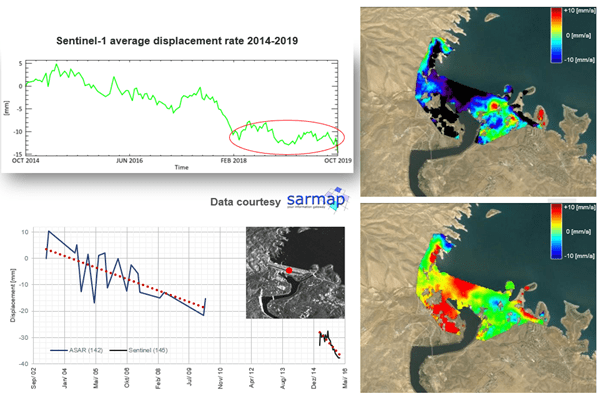
Figure 10: Stability monitoring of critical infrastructure: Mosul Dam – Iraq. Top right- Vertical component of displacement. Bottom right: Horizontal component of displacement. The graphs show dam deformation along the sensor line of sight (study by sarmap).
One example of this type of monitoring is that of Mosul Dam in Iraq which was completed in 1986 but was endangered by internal erosion. Any structural failure with the dam would turn out to be a major disaster for Iraq and would endanger life and property downstream, as well as cutting off a vital water supply to the region. Sarmap conducted a dam monitoring mission using ENVISAT-ASAR and Sentinel-1 Imagery, which was later confirmed by simultaneous work done with high resolution TerraSAR-X data.
Area-based Small Baseline Subset (SBAS) was used to analyze the behavior of the Mosul Dam and the surrounding areas in the last decades. Four different stacks of data were used: two ASAR datasets (20m GSD) related to the period 2003 – 2010 and two additional datasets acquired by the ESA mission, Sentinel-1 (15m GSD), from 2015 to 2016. Displacements were decomposed along the vertical direction (up-down) and the east-west direction (horizontal, along line of sight).
The result along the vertical direction is a downwards deformation with a medium velocity of 1 cm/year in the central part of the structure (the dam is sinking down). The results projected on the east-west direction showed the structure is affected by further rotational deformation, which cause a movement on the east direction. It is interesting to notice a clear acceleration that was the result of the analysis using Sentinel-1 scene.
The time-series of displacement of a point selected on the dam structure is plotted as shown in the figure. The displacements are measured along the satellite line-of-sight. We plotted in the same graph the results obtained with Envisat-ASAR and Sentinel data, supposing a linear evolution of the displacement in the time interval between 2010 and 2015. It is interesting to notice a clear acceleration of the Sentinel-1 results. In fact, the red dotted line which represents the linear best fit of the displacement trend of Sentinel is steeper than the green one, referred to the results obtained with ASAR data. After having made the area secure again, restoration work started in 2016, and was completed in June 2019. As a result of the restoration, the displacement (as well as the collapse risk) was reduced (as shown by the red markings in the graph).
Conclusion
While manual mapping of certain items, such as roads, rivers, fields, and trees has been replaced by automated methodologies, there are still numerous other features that geospatial analysts need to find and map in RS data sets. There is a solution for this challenge as well – the ENVI Deep Learning module. A form of Artificial Intelligence (AI), Deep Learning enables the user to ‘teach’ the software how to recognise nearly any feature or condition in the data set by its spatial, spectral or other characteristics. The module has intuitive tools and workflows that enable users to easily label data and generate models with the click of a button. Geospatial analysts have embraced the ENVI Deep Learning module for the significant savings in time and effort it provides them, compared with manual processes. ENVI Deep Learning can be applied to SAR data, which makes it useful for the defence and security applications presented in this paper.